
Author: therustyfox

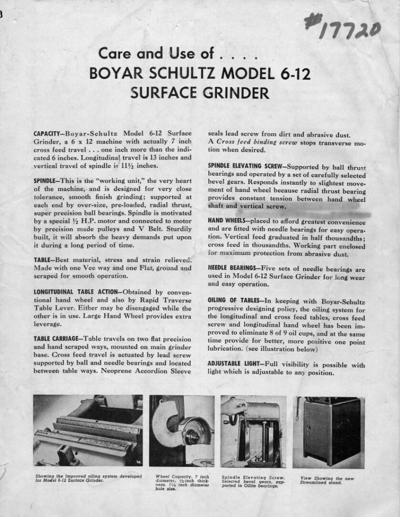
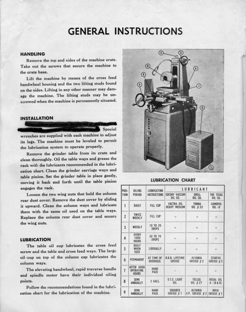
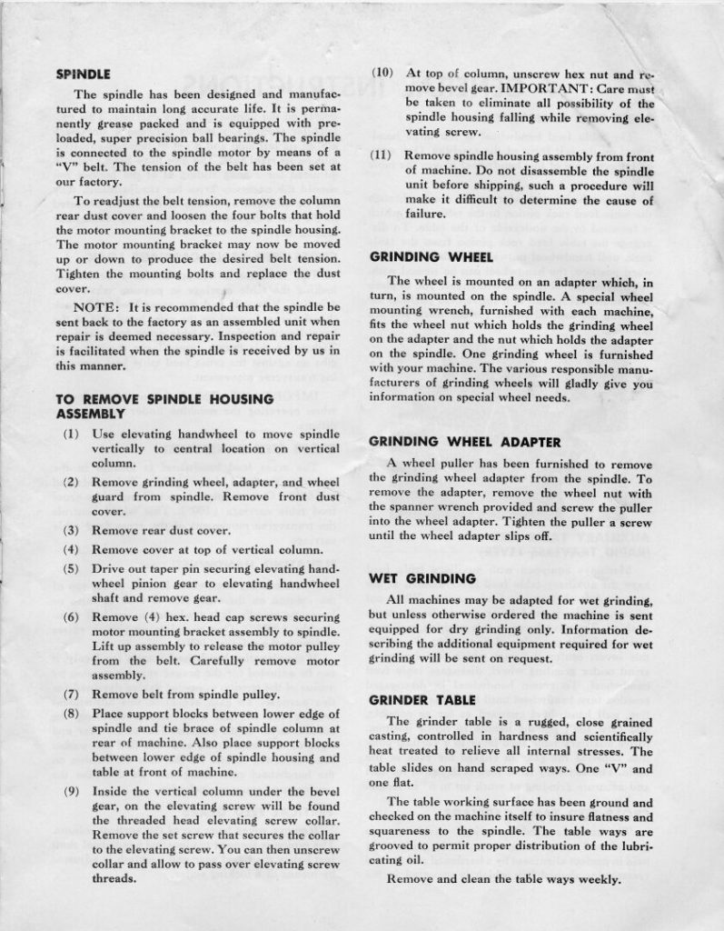
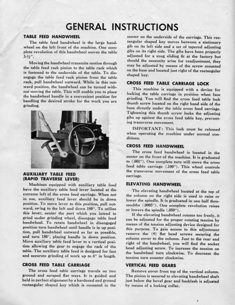
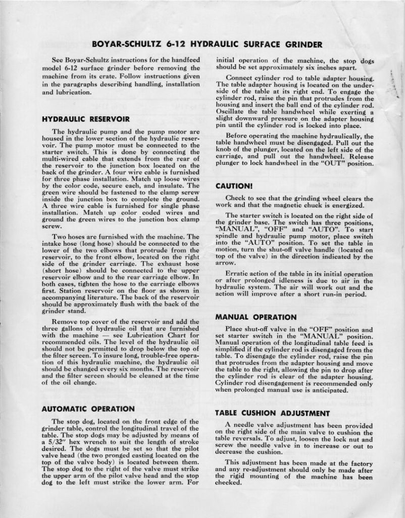
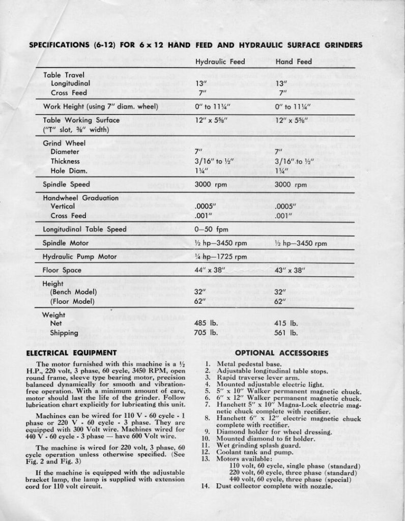
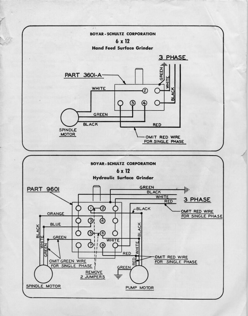
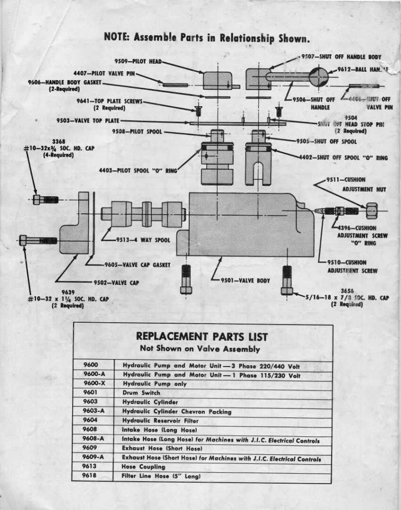
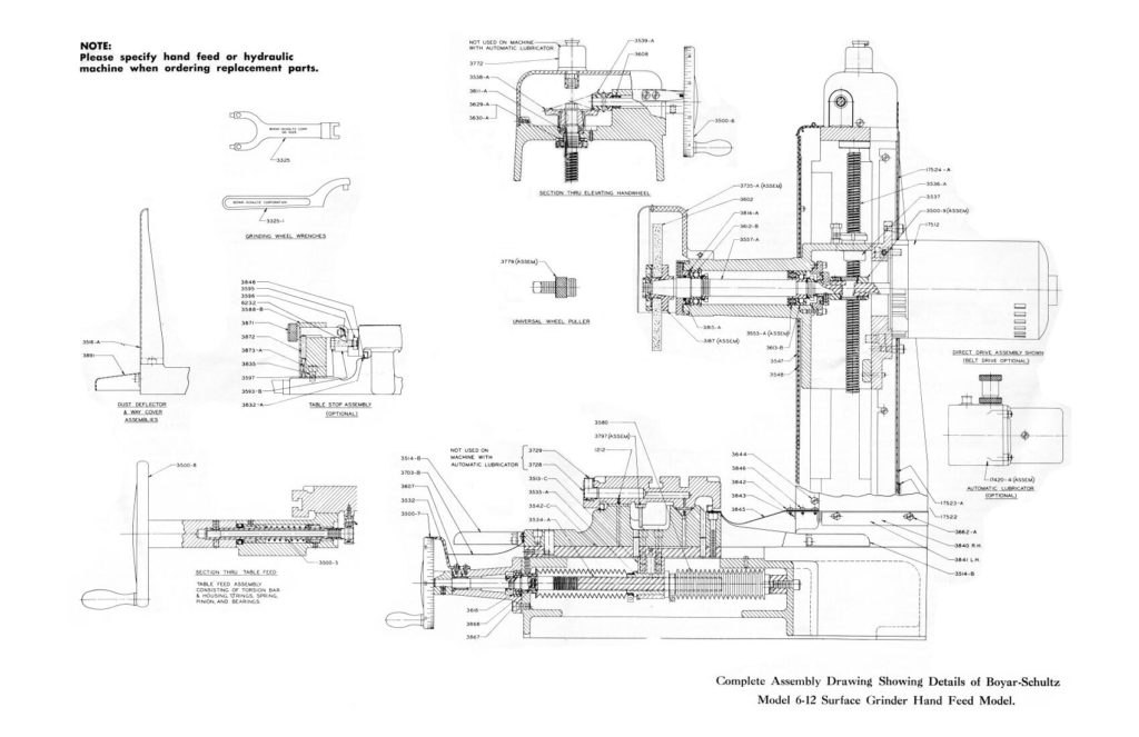
Boyar-Schultz 6-12 Surface Grinder
Scans from an old manual for a BS 6-12 surface grinder that I used to have.
Bridgeport Mill – Power feed Assembly
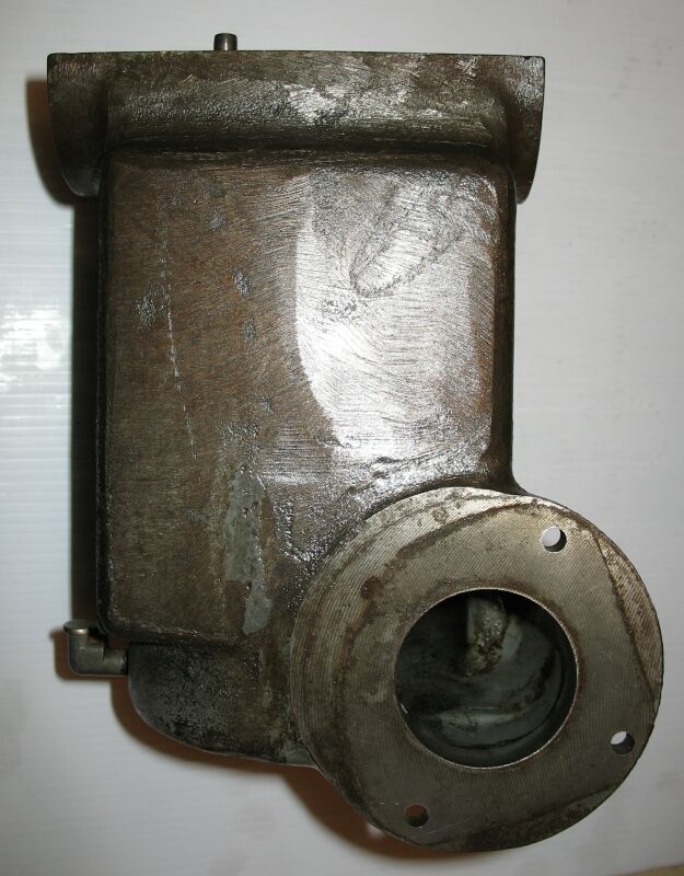
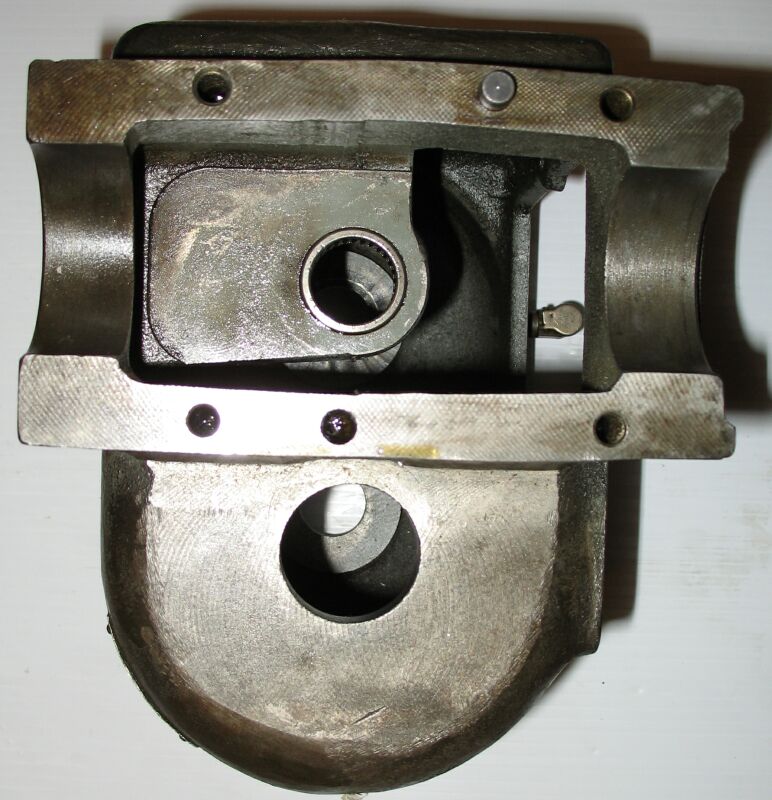
My old (1964-ish) power feed box on my Bridgeport mill had a couple of gears with broken teeth. I took apart the power feed gear box to fix these teeth. Here are some photos I took during the re-assembly. First up — the main case….


And the piece parts. You can see the repaired gear teeth in gold, on the two gears on the bottom row (2nd from left, and 3rd from left).

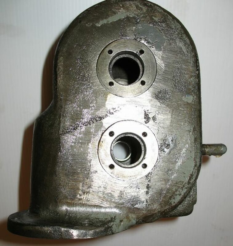
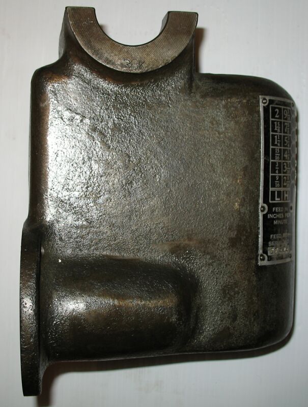
Here are some photos or the re-assembly, in order of re-assembly (mostly). It’s little tricky to get the pieces back in the box, but with a careful examination of the components you can see how the assembly goes together. I used an file/screwdriver to hold the main gear collection in place without actually installing it. This allowed enough movement so that the second shaft of gears could be put in simultaneously.


The completed repair seemed to work just fine. Even though the tooth cutter wasn’t the exact cutter I needed, it was so close that you couldn’t tell. The mesh feels natural, and when I turn the transmission it doesn’t produce any binding or noise or anything that ‘feels’ wrong.

Bridgeport Mill – Power feed Gear Teeth Repair
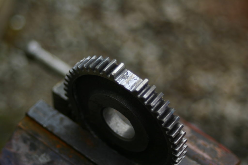
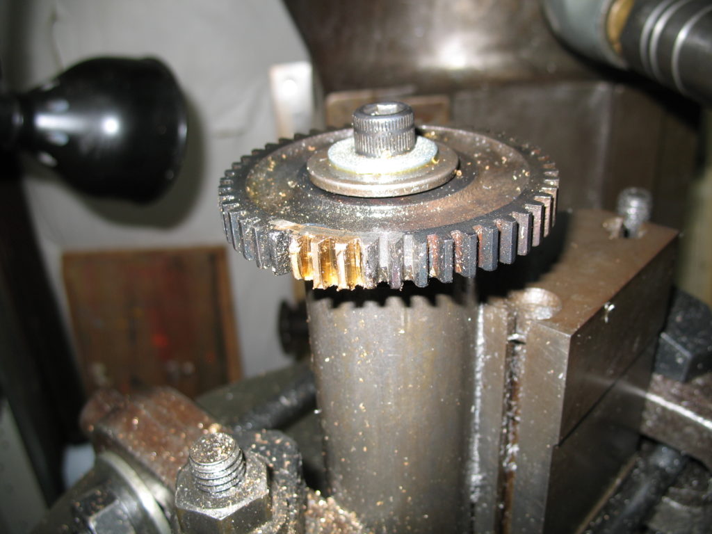
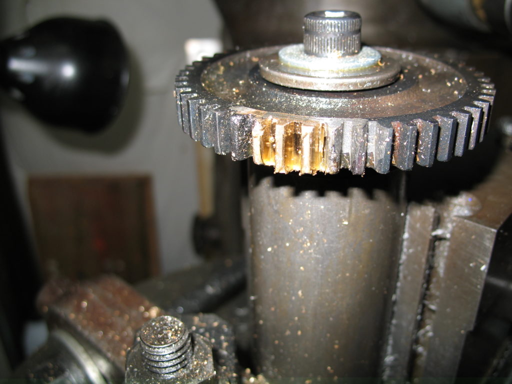
I have an original power feed on my Bridgeport Milling machine. Two of the gears in this transmission have broken teeth, and I decided to try and repair them. Here are the gears in question:

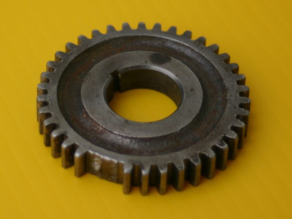
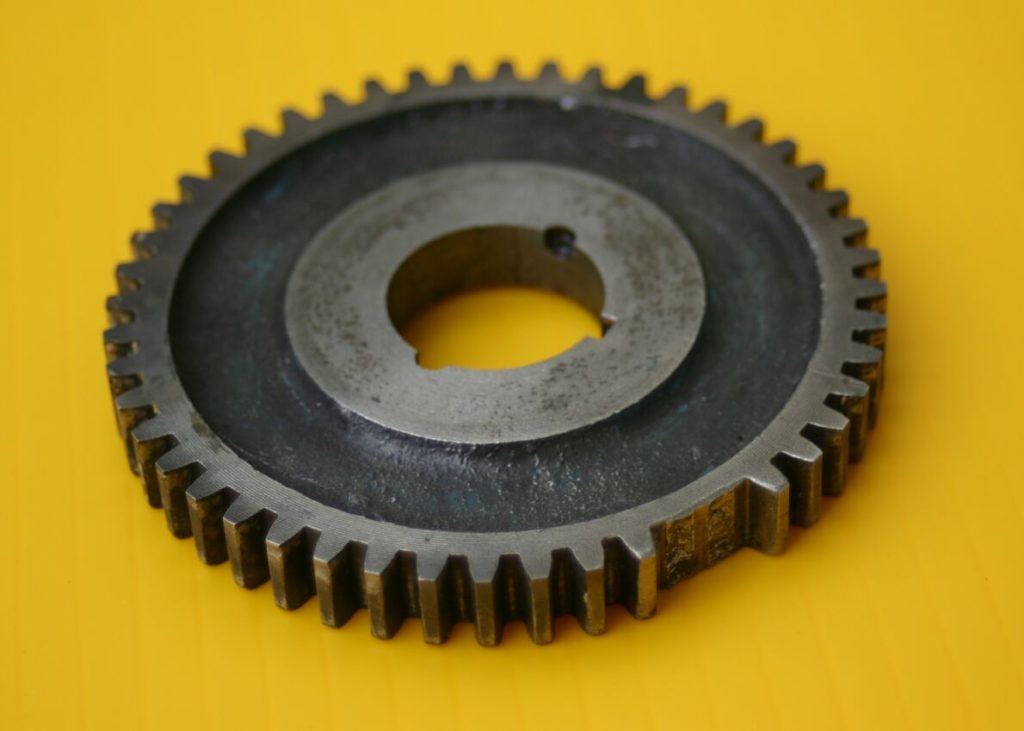
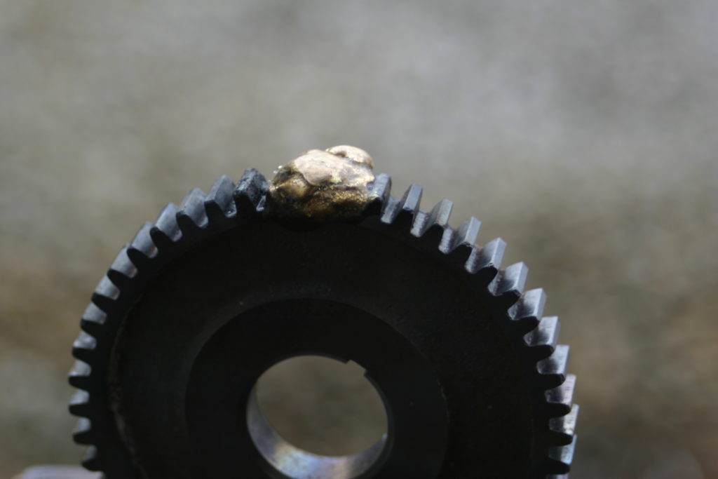
After cleaning up the gap a little, I brazed a big glob between the existing teeth. Yeah, first time brazing.


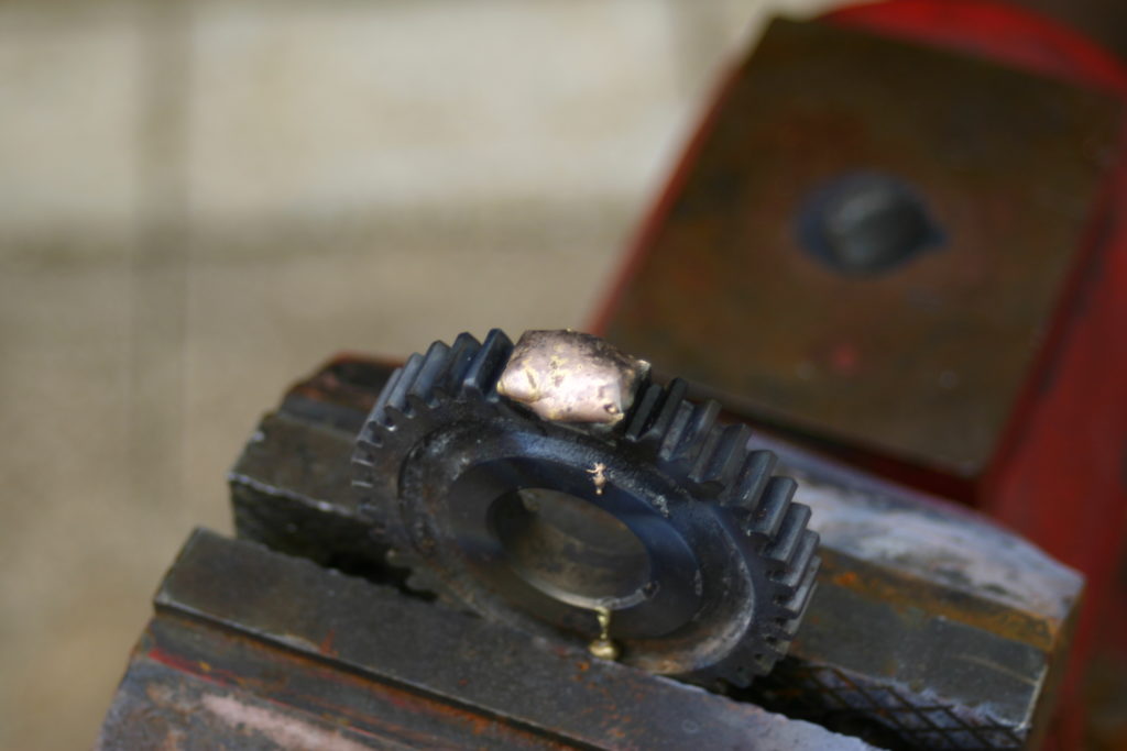
Then, after everything settled down, I stuck in the milling machine and cleaned up the edges a little with an endmill.


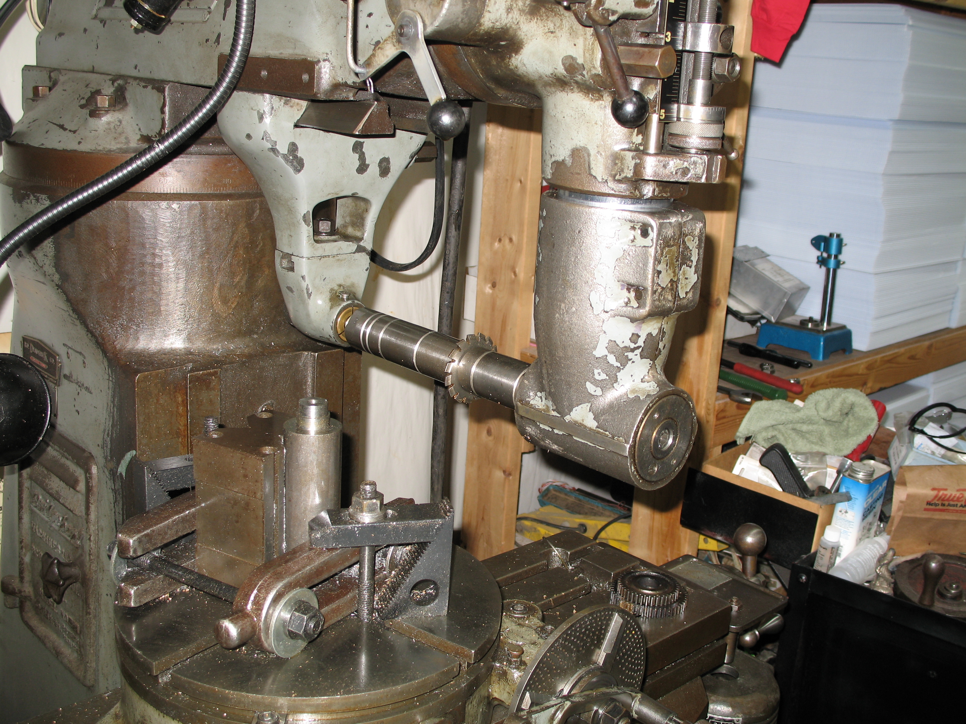
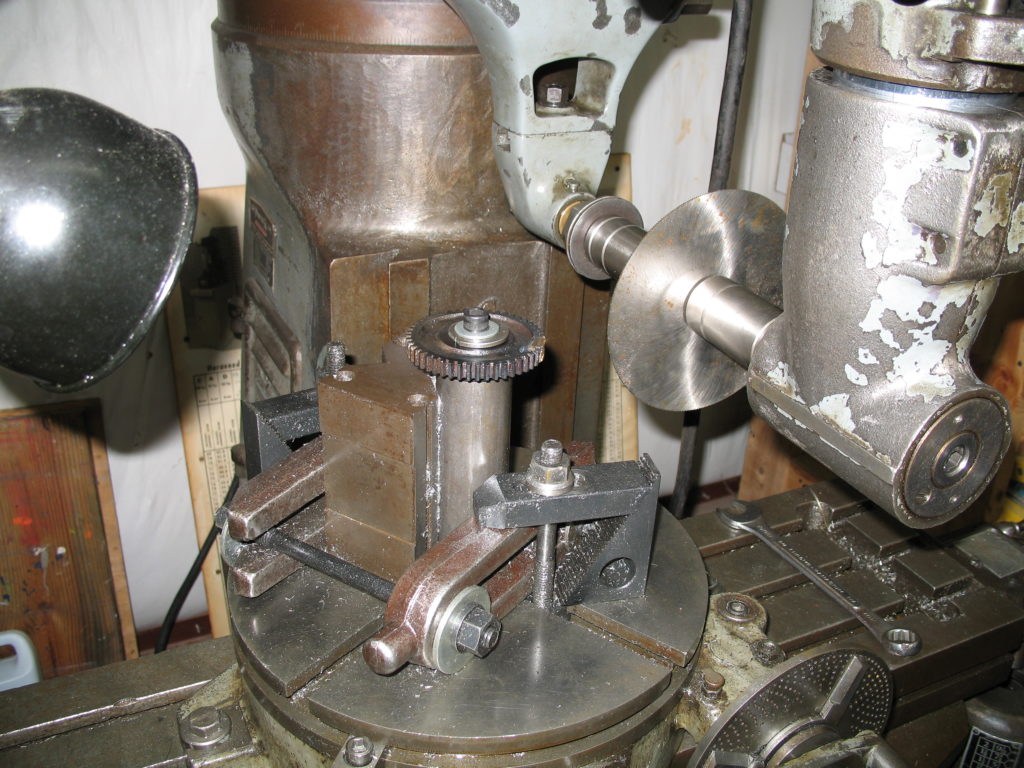
My plan for the cutting was to install a right-angle adapter on my mill, along with my rotary table. Then mount a round bar in the center of the rotary table. I cut it down to fit each gear, then threaded a hole in the top for a bolt, and milled a keyway to hold the gear in place. Here’s the setup (photo actually taken after the cutting):

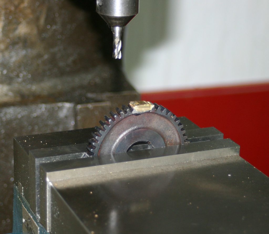
So, up first, I’m going to install a gear, and make some preliminary cuts with a saw blade, in-between the new teeth. Then I’ll change to the gear cutter and go back in for a tooth-shaped cut. I’ve never cut gear teeth, and have no idea how it should be done. This may be obvious to the trained observer.


With some slots cut, I change out to the gear cutter, and line it up. I’m starting a couple of teeth before the cut, and “practicing” moving the table into the cutter on existing teeth. Then I rotate the table the proper angle, and go in to another. When I get to a new-tooth location, I power up and move in for the kill.
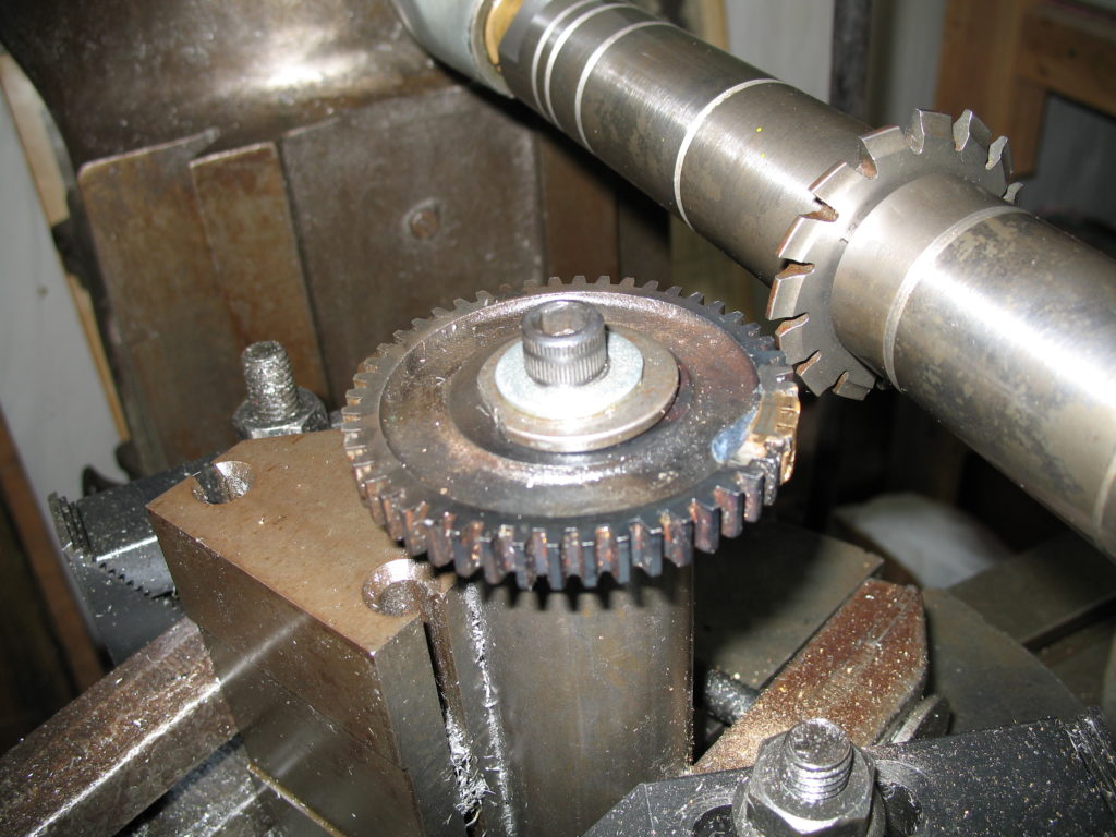
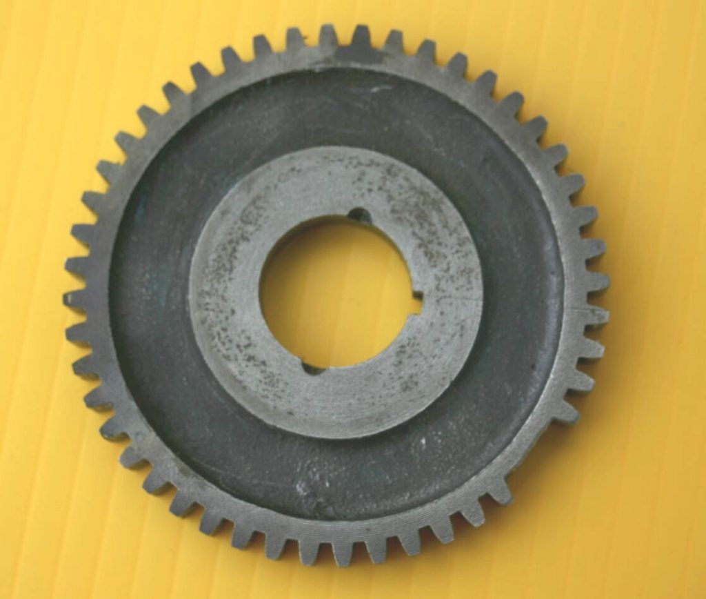
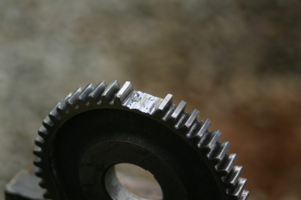
I think, at least, it LOOKS like legitimate gear teeth. Now to install them and check it out.